Tuesday, May 8, 2012

How-To: Make 37 Degree AN Hard Lines

Story and Photos by Matthew Eddy


OEM brake tubing in the US have what is called a 45° double flare at the ends which means the end of the tubing is folded in on itself and flare at 45°.  A flare nut then crushes the tube end against the mating surface to make seal.  After the flare has been crushed it will require more torque to seal seal each time the system is disassembled and reassembled as well as the potential for fatigue cracks to form where the metal has been folded over.  This is fine for the commuter-consumer they aren’t going to be swapping out components from week to week or season to season.  Racers tend to tinker with their cars and may have to dismantle everything or replace components frequently so they need components that are designed to be disassembled and reassembled multiple times.  The 37° AN flare is a single flare is backed up by a tube sleeve that is held to the mating part with a nut and is capable of being disassembled multiple times without fatiguing and since it’s a single flare its actually easier to make than a double flare.  Additionally this method is rated at higher pressures and is held to a higher standard so the system is more robust and can endure the extremes of racing.  It is fairly common for a race team to immediately replace all stock brake lines with the 37° AN flared tubing as part of prepping the car for racing.
The down side of the AN flare is that the components are much more expensive and they also require an adapter to connect them to the stock brake components such as the master cylinder, proportioning valves and ABS block.  Also the tools tend to be more expensive but you can find a 37° flare tool on Summitracing.com for about $30 HERE.   If you decide to upgrade your brakes to the AN fittings then you can save yourself some money and time by only replacing the lines that run from the ABS block  (or the proportioning valves for those cars without ABS) to the calipers and leave any plumbing that might be going from the master cylinder to portioning valves or ABS block. The AN fittings can also be used for routing fuel, vacuum lines, and various other fluids.  Make sure to use STEEL fittings on the brakes or any other high pressure hydraulic systems and you can use aluminum fittings for anything else.

It is pretty easy to convert to AN flared lines but there are a few more parts you need to buy.  I would suggest getting stainless tubing and an appropriate tubing cutter because the $5 Acme Autoparts special will just cry when you try and cut a stainless line with them; they are barely adequate to cut a regular steel line.  Try this one from Mcmaster-Carr: part number 2764A14.  I haven't use this particular one but it does say its for stainless and titanium.

Step 1:  Cut the stainless tubing to length and deburr the ends.  PUT THE HARDWARE ON THE TUBE!  Easy to forget this step you get so excited about flaring the brake line and forget to put the hardware on.  So put on a TUBE NUT, then a TUBE SLEEVE.  Make sure they are facing the right direction.  See pictures at bottom. 

3/16" Stainless Brake Line Cut and Deburred.


Step 2: Clamp the tube into the flaring tool.  It should be sticking a little above the surface of the tool.  The one pictured below is from Summit Racing.  You can find it HERE.

Summit Racing 37 Degree Flaring Tool


Make sure you clamp this down TIGHT.  If its not tight enough the tube will just slide out.  I used a wrench as shown below to get it extra tight.


Use a Wrench to Tighten Flaring Tool.

Step 3: Flare it!


Summit Racing 37 Degree Flaring Tool in Action.

Successful 37 Degree Flare
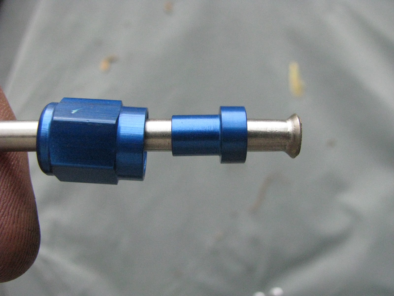
Here is a picture with all the hardware on behind the flare.  These are aluminum fittings, so this isn't to be used for brakes.  The steel ones usually are plain zinc. Left to right are the tubing nut with the threads on the right side followed by the tube sleeve.  The sleeve will be beveled on the side that will sit behind the flare. 


37 Degree -3AN Fittings on Stainless 3/16" Tubing.

37 Degree -3AN Fittings on Stainless 3/16" Tubing.

37 Degree -3AN Fittings on Stainless 3/16" Tubing


The adapters you will need to connect these to the master cylinder for instance look like this.  Most domestic car makers use 3/8-24 (I think) so need this adapter HERE.  Japanese tend to use M10x1.0 so you use this adapter HERE.  These adapters simply screw into the MC or proportioning valve then the new AN fittings screw to these.

Tuesday, May 1, 2012

Baffled Oil Pans Explained

Story and Photos by Matthew Eddy

Outside View of Baffled Oil Pan for 5.0L Mustang


Normal production cars have what is called a “wet sump” meaning the majority of the oil is stored within the oil pan.  A pick up for the oil pump is located in the oil pan and sucks the oil up to lubricate critical areas within the engine.  This system is used because it is simple and cheap to manufacture and is more than sufficient to meet the needs of the commuter consumer.  However, in motorsports the car and engine are going to be subjected to high g-forces for an extended period of time which the wet sump system may not be able to cope with.  For example, in a long continuous high g turn, the oil will slosh to one side of the pan away from the oil pick up.  No oil gets sucked up and starves the engine which leads to excessive wear and catastrophic engine failure in a pretty short period of time. 

The best method to prevent oil starvation is to go with a dry sump system.  This is used in pretty much all the top racing series cars such as Formual 1, NASCAR, Indy, and American Le Mans.  There is an oil pan but it has a very limited capacity and the sump pump basically sucks all the oil out as fast as possible and stores it in a oil reservoir the is external to the engine. Oil pressure is maintained by feeding the oil from this external oil tank back into the engine so the engine is never wanting for oil.  An added benefit of this system is since the oil pan is very low profile, the engine can be lowered to lower the cars center of gravity.  Unfortunately these systems are very expensive.  A bargain basement pump will run you at least $800 and could run upwards of $2000.  Not to mention a new, possibly custom, oil pan, lines, oil reservoir and more. 

Most weekend warriors can’t justify a dry sump system especially if you are just a track day junkie who doesn’t really have a prepped car but there are a couple lower cost alternatives.  One is to get or make a baffled oil pan.  This will limit how much the oil able to slosh around and hopefully keep it where the pump can suck it up into the engine.  Simply put a baffled oil pan will has chambers that make it easy for the oil to travel toward the oil pick up but difficult for it to get sloshed the other way. Also, they tend to increase the capacity of the oil pan so that more oil will be available in the whole system. 

Below you can see a picture of a Ford Racing baffled oil pan out of a 5.0L Mustang.  This one is used mainly for drag racing but the concepts are the same between drag and road track with some design differences to account for lateral acceleration (g-forces experienced while cornering).  

Baffled Oil Pan from a 5.0L Mustang

You will notice the oil pan has two compartments, a shallow on the right side of the picture and a deeper one on the left.  The reason for the compartment on the right (which is the front of the engine) is to allow space for the oil pump.  The hump that separates the two compartments is required to clear the front cross member that goes under the engine.  In the left compartment is a square chamber that that is designed to trap oil and that is where the oil pick up is located.  At first you may be wondering why is seems to be cordoned off, but what is difficult to see in the picture above are the trap doors that only open inward to allow oil to enter the chamber but not exit (see picture below).  A few other features to note are the lips at the top of the chamber and also one on the left side of the center hump.  These lips prevent the oil from splashing up and out of the camber.  The pan is designed such that for the oil to travel from the left or right side of the pan (up and down in the picture), it must pass through the oil pick up chamber where it will be trapped.  


Baffles in Oil Pan
Above you can see a close up of the baffling in the oil pick up chamber.  The doors can only open inward which will allow the oil to enter but not exit.


Oil Scraper in Mustang Oil Pan
The feature pictured above is called a scraper.  As the crank spins, beads of oil are flung around the inside the engine.  The scraper catches most of these to prevent the oil from going up into the cylinders and instead returns it to the pan.  


In the near future I plan to make one of these for my V6 MR2 and when I do so, I will be posting a "How-To" article.

Friday, April 6, 2012

How-To: Coil-Over Conversion
Story and photos by Matthew Eddy

Over the last year I have slowly been prepping my 91 Toyota MR2 for NASA (National Auto Sports Association) Time Trials and eventually race in the Performance Touring series.  Last summer I swapped in a 3.0L V6 and over the winter I have built and installed what I am calling a coil-over conversion; converting the stock struts to coil-overs. 

What may not be clear to all my readers is what coil-overs are and what benefits they bestow over struts since they seem very similar.  If you are purchasing a coil-overs, especially good ones, you are pretty much guaranteed that the dampers and the springs are going to be well matched.  Secondly, coil-overs allow for ride height and corner weight adjustments.   Also they have common spring sizes so it would be easy to swap out springs to fine tune the suspension for individual tracks or if you make other modifications.

Measure First

Before doing this conversion check and see how much clearance you have between the front wheels/tires and the strut housing.  On the MR2, the front spring sits above the wheels and the strut housing is only 1/4" from the wheel.  In most cases you will need to either get new wheels with a larger offset or wheel spacers.  I installed 12mm spacers and new longer wheel studs.  Replacing the wheel studs is pretty easy, especially if you have an impact.  I have posted a video on youtube that shows how to do it here.  I bought both teh studs and spacers on ebay.  To find the spacer search for "hubcentric MR2" and they are usually priced at about $60 pair.  The wheels studs were $35 for 10pcs.  Also, keep in mind that you will need to get new front end-links with this conversion because the bracket is being relocated.  You can deal with this one of two ways; buy Powergrid Endlinks which can be ordered at custom lengths (you will need 5.5" center to center), or cut and weld the stock ones but the stock ones are probably so old and rusty you are better off getting new ones anyways.

Powergrid End links.  It might be hard to believe, but these aren't new, they have been on my car for 2-3 years.


Next, measure your current ride height for baseline for future adjustments after installing the coil-overs.  Park the car on a level surface and measure from the ground, through the center of the wheel to the lip of the fender.  Also measure from the center of the hub to the fender lip.  If you have any fender damage or rust that might make these measurements unreliable pick another point to measure to.  WRITE THIS DOWN, or at the very least, text message yourself.  You will want this information later.
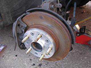
New Studs and 12mm Spacer.


Strut Preparation

The following write up is specific to the MKII MR2 but is still applicable across many makes and models.  One major difference you may encounter is that many cars cannot take strut cartridges.   In the MR2, I can remove the actual damper from the strut housing itself but I do not believe this is a common feature.  If you find this is the case with your struts you have one of two options.  Convert the strut to accept the coil-over sleeve or convert the strut to accept cartridges.  I will address this a bit more at the end of the post since my suggestions will make more sense after you see what is involved.

It might be a good idea to buy an old used set of struts to work on that way if you mess them up some how or the project is more involved than you anticipated you can take as much time as you need.

Strut Diagram - parts of the strut.
Strut Diagram - Distances to measure
See the diagram to the left as a reference for the terms I use for the various parts of the strut. 

1. Disassemble the strut and remove the upper mount and spring.  Second, take measurements.  See my video posted on youtube that shows how to disassemble struts HERE. Reference the diagram on the right.  


2.Measure the overall length of the strut, the length of the body, the distance from the end links bracket to the end of the strut (if applicable) (G or F or both), the shock body diameter (A),  length of the strut rod (D), the diameter of the strut end (B), and distances to other brackets you may have on the strut body.  Also measure the length of the spring, and the thickness of the upper strut mount.

MR2 Struts in Before Being Disassembled.

Disassembled Struts with Spring Perches
3. Cut off the spring perches and grind the housing "smooth."  For the MR2 front strut you will also need to cut off the sway bar end-link bracket.


3a (Optional) - To convert struts that don't usually take cartridges you can convert them to cartridges by drill a small hole near the bottom of the strut to relieve the pressure, then cut off the top of strut to remove the guts.

Disassembled Struts with Spring Perches Cut Off.

Struts Close-up; Spring Perches Cut Off. You can see the gland nut just above the grounded down area.
4.  Put the strut housing into a vice and remove the gland nut with a monkey wrench.

Removing Gland Nut From Strut.

5.  For the front struts, weld the front sway bar bracket just above the knuckle bracket.  Then weld a bead around the strut for the coil-over sleeves to sit on.  For the rear struts, the sleeve will also sit on the sway bar bracket, and you should weld a bead around the strut at that location. 

Weld a bead around the struts for the coil-over sleeve to sit on like this.

6. Cut the bump stock bump stop in half.   More than likely you will be lowering the car which means you will be decreasing the travel of the shock so cutting the bump stop in half will give you a little more travel.

7. (Optional) Sand blast and paint the strut housings.  I would also suggest grinding off any sharp features.  That will reduce the chances of the paint chipping or peeling.  For instance there are little tabs on the knuckle bracket that should be ground down.  After painting them, us caulk or silicon to fill in the gap around the top of the knuckle bracket.  This will prevent water and debris from collecting there and causing corrosion in the future.  I used a special caulk that is applied before powder coating (see the second picture below).

Stock Struts Sand Blasted.

I Have Applied Caulk to the Above Area.

Strut Assembly

I have compiled parts list with prices so you can have an idea of what you need and how much it will cost.  I have not included the cost of the struts or dampers (aka shocks).  For certain parts I have included links to where you can buy them. 

Parts List:

Coil Over Parts - (Left to right) Gland Nut, Lock Nut, 1" Washer, Strut Cartridge, Strut Housing, Top Mount, o-ring (center of pic), Coilover Sleeve, lower Spring Perch, Upper Spring Perch, Spring.


2.5" Coil Spring Tops - Upper Spring Perch(2 sets): $64 total (with powder coating)
Springs – Fronts (Set of 2) (Eibach, 250# 8”): $103 – bought as Edelbrocks on Summit Racing
Springs – Rear (Set of 2) (King, 400# 10”): $43 – bought on ebay, used
O-rings (8 total): $4 (local hardware store)
18mm Washer (6): $2 (local hardware store)
1" Washer (2): $1.50 (local hardware store) 
Light Weight Oil (engine oil, shock oil): $4 (local autoparts store)
Total: $334

Part List Notes:

Spring Rates: Not sure which spring rates to use?  Check out my blog posting about choosing spring rates HERE.  For my MR2 - which I drive to a from the track/autoX, I choose 250 in/lbs front, and 400 in/lbs for the 

Coil-over Sleeves:  I used 5" sleeves because I am using sway bars and that's probably as low as you can move the front sway bar bracket.  I would not suggest going sway barless because there might be a time that you actually want a sway bar.  Also you shouldn't need to get more than 5" of travel that I can think of.  However, on the rears, you can move the sway bar bracket down 2" and get a 7" soil-over sleeve.  

2.5" Coil Spring Tops:  You will need to measure the diameter of the strut cylinder and the guy will customize the inner diameter for you.  I would also suggest getting the parts powder coated to protect them from debris.


Assembly


1. Put (1) o-ring on the strut housing (about 2-3" from the top of strut housing)
2. Slide coil-over sleeve over o-ring.  The sleeve should slide over the o-ring and be moderately tight.  If the o-ring is just to thick, wrap the strut tower with electrical tape about 1" above the weld bead.  The purpose of the o-ring or electrical tape is to remove play between the sleeve and the housing and prevent the sleeve from spinning when adjusting ride height. 
3. Take a second o-ring and force it into the gap between the strut housing and sleeve from the top. See pic below.

Using a flat head screw driver to insert o-ring.  Here the gland nut is already on, but its a lot easier to do this before installing gland nut.
4. Screw the lower spring perch onto sleeve (can be done later).
5. Put the strut housing into a vice, and protect the paint with rags.  Pour about 3oz of oil into the housing.  The oil fills the gap between the cartridge and the strut housing to prevent heat building up in the shock.  I prefer not to use tranny fluid or gear oil because of the smell.  I used some engine oil because it was convenient.
6. Insert strut cartridge.  Check oil level, and fill as necessary.  You want the oil to be about .5-1" from the top.
7. Apply some anti-seize to the gland nut and screw it on.  First by hand and then tighten with a monkey wrench.
8. Put spring on. 
9. Put bump stop on the shock cylinder.
10. Put top spring perch on
11. Put (1) 1" washer on (FOR THE FRONT STRUTS ONLY).  This is acting as a spacer so that the top spring perch contacts the bearing portion of the front strut mount.  See below photos.  I also added bearing greases here to prevent corrosion and wear.  This section will be turning with the wheels.  Though I have two pictures, each showing a washer, you only need to use one washer.  The pictures below are just to demonstrate where the washer will sit. 


Washer sitting on spring top.

Where the washer will sit on the strut mount.
12. Put the strut mount on.
13. Put (3) 18mm washers on (FRONT ONLY).  The stock upper strut mount would usually sit under the mount and without it there is some play between the mount and the locking nut that holds this all together. 
14. Screw on the locking nut on the end of the shock shaft.  The hardest part about this is that the shock will want to spin.  You best bet it to snug it up by holding the shaft with your fingers through the coil.  Once it starts to spin you can try wrapping a piece of rubber around the shaft and grip it with vice grips.  Get them as tight as you can.  Don't worry, you won't be able to get it super tight, but it should be good enough. 


When you are done they will look something like this.


Coil-over Conversion.  Fronts for a MKII MR2 with 10" springs.  I later switched to 8" springs.
Here is a pic of them mounted in the car.

Front Coil-overs mounted on the cars.

For struts without gland nuts you can weld on the strut without removing the inner shock but take a few precautions such as welding in short durations.  Do not weld weld near the valves (toward the top or bottom of the strut). But the better option will be to cut off the top of the strut, remove the damper and then weld a threaded collar that will allow you to swap out strut cartridges.  You will probably have to do some research and find a cartridge that is the proper diameter and length to fit. 

Adjusting Ride Height

 When I installed mine I moved the lower spring perch up to hold the spring against the top mount, then mounted the coil-overs on the car.  Measure the ride height from the ground to the fender as described above.  Remember to do this on a level surface!  If, by magic or math you got the ride height perfect on the first go then make sure everything is tightened up and take it for a test drive.  If you want to make adjustments then jack up the car, remove the wheel and measure the distance from the lower spring perch to some point on the strut.  Then adjust the position of the lower spring perch to change the ride height. Below you can see how I measured using a metric measuring tape.  I find metric to be much easier than figuring out what fraction of an inch I was looking at. I was using the knuckle bracket as my reference point.  In this cse I was at 73mm.  I wanted to reduce my ride height by 1".  25mm = 1" so to lower the car 1" I need to moved the lower spring perch down until I measure 48mm.
 
 
Measuring the Distance of Lower Spring Perch to Reference Point on Coil-Over.

Sure enough, I dropped the car and I was at exactly where I wanted to be.

If you have questions, please feel free to ask them in the comment section below.  


Fine Print: You are responsible for your own safety and modifications to you car.  I am not responsible for any damage, injury or death that may result.  Follow these steps at your own risk and if you aren't sure you are doing something safely then don't do it. Always use proper safety equipment.  Modifying or changing existing products on your car is risky and not suggested by the manufacturer so any damage, injury or death is your own responsibility.  Do not attempt if you don't feel you can accomplish this safely.  Make sure to check all the bolts are tightened properly and test the car before driving it.


Saturday, March 24, 2012

GIVE BLOOD!

I donated blood today, and I would encourage anyone who is able to donate to please do so.  The American Red Cross always needs donations, and you can help save a life.

Check out the American Red Cross website to find donation sites:  http://www.redcross.org/

Thank you,
Matt


Wednesday, March 21, 2012

Suspension Series Part 1 - Shocks and Springs

Selection of coil-over springs.


To avoid confusion, I want to be clear that I am not a suspension expert.  I am preparing my MR2 for NASA HPDE (High Performance Driving Events) with the intention of working toward my time trial and competition license.  Over the last couple months I have been reading articles and books about suspension design and tuning so that I can make my car as good as I can.  The more I learn the more I will share.

It seems that a lot of people confuse the purposes of the shocks and springs.  The spring should be determining the “stiffness” of the suspension not the shock.  That is not to say that their functions aren’t interrelated and as such it is very important that they complement each other in order for them to be effective.  Primarily the function of the spring is to keep the wheels in contact with the ground.  In short the springs allows the wheels to move vertically over bumps and into divots to maintain contact with the road.  The spring is actually the load bearing component of the suspension and is a boundary between what is referred to as “sprung” weight and “unsprung” weight (see future articles).  The shock’s, or the damper’s, sole purpose is to control the motion of the spring.

When a spring is compressed and then released, it will bounce or oscillate.  The same can happen to an unrestrained spring in a car and in such a case you will see the wheel literally bouncing after it hits a bump or pothole.  It’s not very often you will see this on the street, but I have seen it a few times.  The damper is designed to control the spring to prevent this from happening.  Ideally, when a wheel encounters a bump it will travel over it causing the spring to compress.  As the bump tapers off, the wheel will follow the profile of the bump back down to the level surface of the road and then its vertical motion will cease.  In other words the natural tendency for the spring to oscillate will be limited to one up and one down motion also known as a cycle.  This is achieved by a properly designed and matched set of springs and dampers. 

Another way to think of this relationship between the spring and the damper is to consider this system separate from the car.   If the spring is compressed then released it will want to bounce up and down a few times.  As I described above, paired with the right damper under the same test, the spring will be compressed and when released will rebound back to its uncompressed length and stop.  Now imagine that we replace the spring will one that is much stiffer but we don’t change the damper.  When we compress the spring we will need much more force to do so.  The spring is now storing or absorbing much more energy and when we release it the spring will rebound with a lot more force.  Now the spring is too strong for the damper and it cannot be controlled.  The spring will oscillate a couple times more than we would like it to because the damper is being over powered by the spring. This is an example of an under-damped car.  Now if we instead swapped out the spring for one that is much softer than the original, then this condition would be called over-damped.  When the spring is compressed and released the spring will rebound slowly; too slow to react to changing road/track conditions.  In a car, imagine hitting a bump and the spring can’t compress because the damper is to stiff.  This artificial increase in spring rate isn’t beneficial to the handling of the car because even minor bumps will be  

Adjustable Shocks

Considering the above examples, if you get stiffer springs for your car but use the stock dampers, then you may be under-damped depending on how much stiffer your new springs are.  This is precisely why adjustable struts/shocks/dampers are available.  You can buy adjustable dampers and throw on a new set of springs and tune the damper to them.  If you decide you need to change out the springs, then you can quickly make adjustments.  Some racers change their spring rates to suit specific tracks or in the case of an Auto-x’er they may change out their springs for different lot surfaces.  Theoretically, once you have set the dampers to the correct stiffness for your springs, you shouldn’t have to change them, but that isn’t so in the real world.  Different tracks and surfaces will need fine tuning.  However, it’s not likely your adjustments will vary much from the theoretical “ideal.”  Even adjustable dampers have a specific working range.  If you choose springs outside that range then you will need to change them out. 

One major drawback of adjustable dampers is that the adjustments can be very inconsistent and aren’t usually repeatable. Dennis North, a highly successful Auto-X’er has tested thousands of shocks and repeatability.  Unless you pony up big bucks for Penske’s, the adjustability is pretty much useless.  No two shocks from the same manufacturer are alike.  Sometimes adjusting them a little stiffer has the complete opposite effect and vice versa.  His suggestion, for the serious yet budget conscious racer, is to get Bilsteins which are re-valvable. This means you can disassemble the shocks fairly easily, change out the internal valves which control the compression, and rebound to tune the shock.  Obviously having to disassemble the shock is not as convenient as an adjustment knob, but it is more customizable. 

Another drawback of most adjustable dampers is that they will only adjust rebound, compression, or both simultaneously.  Compression is how much resistance the damper has when the spring/damper is being compressed and rebound is when the spring/shock is extending.  If you can only adjust one you might find yourself under/over damped in compression but OK in rebound or vice versa.  Higher end dampers will allow you to adjust both independently but they also tend to be quite a bit more expensive.  So the end of the story is, if they aren’t going to be consistent, it probably isn’t worth spending the extra money.

Tuesday, February 28, 2012

Alfa Romeo Giulietta - aka Dodge Dart


Some of you may know that the Dodge is re-releasing the Dart later this year to fill the compact car opening in its vehicle line up.  Though the body will be Dodge its bones will be Fiat; more specifically the Alfa Romeo Giulietta.  Since I am not the die-hard buy American type I am actually pretty excited that Chrysler is using this chassis since the car may retain some of the Alfa’s character.  Even though Alfa Romeos are notoriously unreliable the Top Gear guys still love these cars.  Which means I will definitely take the opportunity to drive one when I get a chance.  I do like the body styling of the new Dart, and I hope its fun to drive.  According to a friend of mine who is a vehicle dynamics engineer with Chrysler said the engineers working on the Dart are trying to preserve the Alfa driving experience.  I hope they do.

I can’t say there are many benefits to living in South East Michigan – like crumbling roads and loose rocks that crack windshields, but I do get to see a lot of the new cars in their razzle-dazzle or flat black paint schemes like this Alfa Romeo Giulietta mule I saw a couple days ago.  I can only speculate what Chrysler’s intentions are with this car; testing for the Dart, Fiat may release the Giulietta in the US, or they may use the platform for a number of other cars.  I heard a newer smaller Jeep model might use this chassis

Alfa Romeo Giulietta test mule painted flat black.

Alfa Romeo Giulietta test mule painted flat black.

Thursday, February 23, 2012

How to Choose Spring Rates

Spring Rates Calculator
Using Suspension Frequency to Help Determine Ideal Spring Rates for your car.

In the right margin of this blog I have posted a spring rate calculator.  It looks like a small excel spreadsheet and it will help you determine what spring rates will work best for your application.  Most consumers who are upgrading their suspension don’t think about spring rates they choose a coilover kit or brand of springs and bolt them on.  They may be basing their decision on opinions or reviews they read online and they may not be getting the best setup for their application.  When I say most consumers, a large majority of consumers are modding their cars for cosmetic reasons and aren’t actually intending to participate in any motor sports.  So for them, the spring rate is inconsequential because they are looking for either a good brand they can brag about or something that is inexpensive.  

If, on the other hand, you are interested in actually participating in some sort of motor sport like AutoX, track days, or racing, then a properly tuned suspension will give you an advantage over your competitors who may have only bought a recommended coilover package.  This isn’t necessarily a bad way to go since there are a lot of good coilover kits out there that are tuned for the car and application.  But understanding spring rates and how they can be used to custom tune your suspension to very specific tracks or your own driving style can give you an edge on the competition.  At the very least it will give you a better understanding of how the suspension works. 

You don’t need coilovers to adjust spring rates, but one advantage of coilovers is that the springs have a standard diameter and you will be able to find a variety of spring rates and lengths online.  Usually the rates will be available in 50lb increments.  This gives you much better suspension tuning options than an aftermarket spring kit that is designed to fit the stock spring locations.  These kits are cheaper since you don’t need to upgrade to coilovers but there won’t be a variety of spring rates available to choose from.

The standard spring rate measurement I will be using is lbs per inch which represents the amount of force in pounds it takes to compress a spring one inch.  For example a 400lb spring will compress one inch when 400lbs of force is applied.  The same spring will compress two inches when 800lbs are applied and four inches when 1600lbs are applied.  To give you some perspective a Ford Focus might have 80-150lb springs, a mildly built Miata might have 300lb springs and a full track car may have 600-2000lb springs.  Obviously the higher the spring rate the harder the ride. Bigger cars will also have stiffer springs since the springs will have to carry the weight of a heavier vehicle.  

It seems obvious to many why stiffer springs would be more desirable, but it may not be obvious to everyone.  A brief explanation is that a stiffer spring maintains to road contact, the car won’t lean as much in a turn, and it won’t bow as much under heavy braking.  The compromise is that the ride quality will be much harsher and that means less comfortable for daily driving. This will be covered in more detail in future articles.

Suspension frequency (SF) describes the natural frequency of the spring in relation to wheel motion and can be used to estimate the appropriate spring rate for various applications.  The calculation isn’t particularly difficult but will require either finding data or taking measurements of the car.  You can also use this to evaluate spring rates of various coilover kits and stock spring packages.  Most passenger cars will have a rate of approximately 1 Hz.  A fairly aggressive suspension setup will be around 2.0 Hz and a track dedicated car will have a frequency of around 3.0 Hz or more.  So you can use this information to figure out where on this spectrum of suspension frequencies will fit your application.  If you drive your car to the track or AutoX event you might want to try a SF a little over 2.0.  It is important to note that you want your rear SF to be slightly higher than your front otherwise the car might start to porpoise; rock forward and backward.  Also keep in mind that you will need to upgrade your dampers (aka shocks) to handle springs that are stiffer if you haven’t done so already, especially if you choose a very aggressive spring rate.   

The spring rate calculator on the right is fairly simple to use.  Figure out what suspension frequency you want, update the vehicle data for your car in the white cells and the ideal spring rate will update in the yellow.  Everything in gray should be left alone and the calculated spring rates will be yellow.  For now none of the cells are protected so you could go in and modify any of them but none of the changes will be permanent.  If you make any mistakes, refresh the page and it will reset the calculator.  The spring rates are calculated for individual corner of the car but since the left and right side should be essentially the same the calculator will only calculate front and rear. If you want some more background information check out the Eibach website.  Please note for a live axle or solid beam axle this calculator will not work.

User Inputs:

Race Weight - This is the weight of the car with fully suited driver, and fuel.  If the car is stock, take the curb weight, add your own weight when fully suited, and a little extra for incidentals.
Weight Distribution Front - percent of the total weight of the car in the front.  You can use stock data to get you close.
Unsprung weight - this is the weight not supported by the springs, so this is the weight of the wheels, tires, hubs, brake caliper, half the control arm, etc.  You can estimate this weight and it will probably be somewhere between 80-100lbs per corner.  Keep in mind that particularly large wheels will be significantly heavier and may push your unsprung weight well over 100lbs per corner.  Since some cars have staggered wheels the unsprung weight from front to rear may be very different.
Spring Angle - if you have a McPherson Strut, you can estimate the angle at 5-10 degrees.  Otherwise you need to determine what angle from vertical the spring/coilover/strut is mounted in the car. 
D1 & D2 - D1 is the distance from the spring mount on the control arm to the control arm pivot point. D2 is the distance from the ball joint to the control arm pivot point.  The units aren't important as long as they are the same (mm, inches, feet, furlongs or whatever). If you have a McPherson strut, then leave these numbers alone since 98/100 is the approximate ratio.  You will see you need to do this for the front and rear.  If you are a Mustang owner and have a live axle, just do it for the front since this is not setup for solid axle setups. 

Everything in gray should be left alone since it is either calculated for you based on the info you entered in the white cells or cell descriptors but I will explain what the various measurements are.

MR - Motion Ratio, this is the ratio of the motion of the wheel to the motion of the spring.  This is calculated by taking D1 and dividing it by D2.  That is why the units of measure aren’t important, since we are using them to calculate a ratio.
ACF (Angle Correction Factor) - This is needed to accurately calculate the how much the spring compresses in relation to the wheel motion.
Front and rear Sprung Weight - In this formula, this is calculated based on the weight distribution and unsprung weight.  In this current configuration, the unsprung weight is considered to be the same for front and rear wheels.  I will update it shortly so that you can put unique values for the front or the rear.
Spring Rates - These are the required spring rates to achieve the desired suspension frequency.  You probably won’t be able to get a 212.3356 # spring, so you will have to decide if you want to with a 200# of 250# spring.  When deciding which way to go, remember that you want the rear SF to be slightly higher than the front, so look at both the front and rear SF before deciding. 

If you have any questions please feel free to leave a comment, and feedback would be appreciated.